Medical PTFE Tubing Liner: How to Choose, Bond, Compare, and Validate It for Catheters
Direct answer
A medical PTFE tubing liner is the usual starting point when a catheter or minimally invasive delivery system needs a low-friction inner lumen for guidewires, balloons, stents, or other devices to pass through.
PTFE earns its place on four grounds: lumen lubricity, chemical resistance, thin-wall capability, and dimensional stability. Friction alone is a poor reason to specify it. Wall thickness, ID and OD tolerance, flexibility, kink resistance, bonding method, sterilization, and the biological evaluation of the finished device all shape the final decision.
Most catheter programs do not stall because PTFE is not slippery enough. They stall because the liner cannot be integrated into the shaft reliably: delamination, wrinkling, lumen collapse, or a usable inner diameter that shrinks below the design target.
What is a medical PTFE tubing liner?
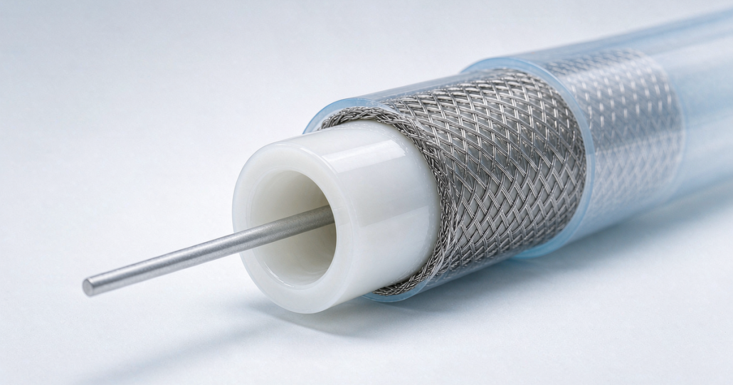
A medical PTFE tubing liner is a thin polytetrafluoroethylene tube placed inside a catheter, introducer, sheath, or delivery system. It creates a smooth, low-friction lumen for another device to advance through.
In a typical shaft build the liner is one layer among several. Polymer jackets, braided or coiled reinforcement, radiopaque markers, distal tips, adhesives, and external hydrophilic coatings sit around it.
Design teams look at PTFE liners for guide catheters, microcatheters, introducer sheaths, delivery catheters, and other minimally invasive devices where internal sliding force decides how the device behaves in the physician’s hands.
For a closer look at what separates medical-grade stock from general-purpose tubing, see medical-grade PTFE tubing.
Why use PTFE as a catheter liner?
PTFE reduces internal sliding resistance
The lumen surface sets how easily a guidewire, balloon catheter, or stent delivery system travels through the shaft. A lower-friction liner cuts resistance in both directions, advancement and withdrawal.
The difference shows up in long, narrow, or tortuous paths, and wherever devices are exchanged repeatedly. Friction there turns into higher insertion force, less predictable movement, and a shaft that fights the physician.
PTFE holds its place in liner work because the surface is very low friction and chemically resistant, a combination that suits catheter lumens and delivery systems.
Vendors working in this space describe the same pattern: extruded PTFE liners are specified mainly for the friction and chemical profile of the lumen surface, not for structural support.
PTFE can preserve usable lumen space
A thin-wall liner buys back usable inner diameter while the outer diameter target stays fixed. In small-diameter catheters that trade-off drives the design, because every increment of wall thickness competes with space needed for the reinforcement and the outer jacket.
Film-cast PTFE is usually the route chosen for ultra-thin constructions, where cross-sectional space and tight dimensional targets matter most. Nordson MEDICAL covers that reasoning in its white paper on film-cast PTFE liner.
PTFE resists many chemical exposures
PTFE is chemically inert and resists attack from a wide range of media. Inside a lumen that can mean exposure to process chemicals, contrast media, saline, or drug solutions. Compatibility still has to be verified against the actual fluid, concentration, dwell time, and finished device configuration.
PTFE introduces a bonding challenge
The low surface energy behind PTFE’s non-stick behavior is also what makes it hard to bond to most thermoplastic catheter materials.
Liner suppliers therefore work with chemical etching, a tie layer, a strike layer, mechanical retention, or a validated combination of the four.
Both extruded and film-cast liners may be etched before assembly and bonding. A strike layer improves adhesion by flowing into the etched microtexture and raising the effective contact area.
How to choose a PTFE liner
Treat the liner as part of the whole catheter architecture, not as a part number ordered on its own. Start from the clinical task and work backward to geometry, process, and validation.
| Selection question | Why it matters | Typical design implication |
|---|---|---|
| What must pass through the lumen? | Guidewire, balloon, stent, aspiration tool, or imaging component determines clearance and friction needs. | Define target ID from the largest device, plus functional clearance and tolerance stack-up. |
| What is the target catheter OD? | Outer diameter limits available space for liner, reinforcement, and jacket. | Thin-wall or ultra-thin-wall liner may be required. |
| How tortuous is the intended path? | Tortuous anatomy increases the value of flexibility and resistance to buckling. | Consider liner construction, wall thickness, and whole-shaft flexibility. |
| Must the liner bond to another polymer? | PTFE does not typically bond easily without surface preparation. | Specify etched surface, tie layer, strike layer, or retention method. |
| What reinforcement is used? | Braids, coils, and hypotubes affect reflow, compression, and liner behavior. | Validate wrinkling, lumen collapse, and delamination during forming. |
| What sterilization method is planned? | Final device performance lives at the material interfaces, not in the PTFE alone. | Test the finished sterile device after the intended sterilization cycle. |
| What is the body-contact category and duration? | Biological evaluation depends on the final device and its use conditions. | Build an ISO 10993-1 risk-based evaluation plan for the finished device. |
Start with the required inner diameter
Do not size the liner ID to the nominal diameter printed on the guidewire or device. Set it against maximum device dimensions, geometric tolerances, lubricant or fluid conditions, bending, part-to-part variability, and the force the procedure actually demands.
Take a 0.014 in guidewire system. The liner has to clear the wire’s real maximum diameter, allow for device exchanges, and absorb the friction increase that appears once the catheter is bent. A lumen that fits on paper often fails in a tortuous-path bench test.
Balance wall thickness against structural performance
Thinner PTFE walls free lumen space, but they also make the liner more sensitive to handling damage, ovality, wrinkling, buckling, and local deformation during assembly and reflow.
The right wall is not the thinnest one on the drawing. It is the thinnest wall that still meets assembly, mechanical, dimensional, and clinical-use requirements.
Define tolerance before requesting a quote
- Inner diameter and outer diameter
- Wall thickness target and allowable tolerance
- Length or continuous spool requirement
- Straight, tapered, stepped, or custom geometry
- Single-side etched, double-side etched, or unetched surface
- Which liner surface must be bondable
- Required concentricity and ovality
- Cleanliness, packaging, labeling, and traceability requirements
- Planned sterilization method
- Estimated annual volume and development-stage quantity
Extruded vs. cast PTFE liners
Extruded and cast PTFE sit at different points on the dimensional control, strength, flexibility, and assembly-behavior scale. Which one belongs in your shaft depends on where those priorities land.
| Attribute | Extruded PTFE liner | Cast or film-cast PTFE liner |
|---|---|---|
| Primary strength | Often selected for dimensional stability and structural support. | Often selected for very thin walls and flexibility. |
| Catheter fit | Can suit guide catheters and applications requiring robust shaft behavior. | Can suit designs prioritizing flexibility and lumen-space optimization. |
| Manufacturing concept | PTFE is formed through an extrusion process. | PTFE dispersion is coated onto a mandrel and sintered. |
| Bonding preparation | May require etching for downstream bonding. | May require etching and can use a strike layer for adhesion. |
| Main design question | Can it provide the desired precision and support? | Can it maximize flexibility and usable ID without compromising assembly yield? |
Extruded PTFE liners are usually chosen for dimensional stability and pushability. Film-cast liners come up when flexibility and thin walls matter more. Vendors operating in both formats, such as Hydromer, frame the split the same way. Confirm your choice against your exact device architecture and test method before freezing the design.
Etched vs. unetched PTFE liners
Choose unetched PTFE when the priority is the original PTFE surface
Unetched PTFE is the starting point when no bondable surface is needed, or when the design relies on mechanical retention instead of an adhesive or a thermal bond.
Choose etched PTFE when a bondable interface is required
Etched PTFE carries a modified surface intended to improve adhesion. In catheter work the outer surface of the liner often has to bond to another polymer layer while the bore stays optimized for low-friction passage.
- Outer-surface etch is commonly relevant when the liner must bond to an outer jacket or an intermediate layer.
- Inner-surface etch is relevant only when the lumen side requires a later bonding or coating operation.
- Double-sided etch is relevant only when both surfaces must participate in downstream assembly or coating steps.
Specification note. An etch spec is incomplete without four things: which side is etched, the shelf-life expectation and storage conditions, the bond test method, and the materials being joined.
Etched liner storage and the use window after delivery both need managing. Our own guidance on etched PTFE liner storage covers room-temperature storage away from strong light and a defined window for use after delivery. The surface chemistry that makes bonding possible also drives the chemical side of the process, which we cover in PTFE etching for medical devices.
PTFE liner vs. FEP, PFA, HDPE, Nylon, and Pebax
No liner material wins everywhere. PTFE is strongest when low internal friction tops the requirement list. Where processing, thermal bonding, flexibility, cost, or system-level compatibility dominate, another polymer can be the better answer.
| Comparison | PTFE advantage | Alternative-material advantage | Best question to ask |
|---|---|---|---|
| PTFE vs. FEP | Lower-friction liner behavior and strong chemical resistance. | FEP is melt-processable and may simplify thermal bonding. | Is low friction more important than process-friendly heat bonding? |
| PTFE vs. PFA | Strong lubricity and established liner use. | PFA may offer easier melt processing and useful flexibility. | Does the design need a PTFE-level liner surface or a more processable fluoropolymer? |
| PTFE vs. HDPE | Lower-friction, chemically resistant fluoropolymer surface. | HDPE may offer cost and process advantages in some constructions. | Is the performance gain worth the added bonding complexity? |
| PTFE vs. Nylon | Lower surface friction and low moisture sensitivity. | Nylon can offer strength and familiar catheter-shaft processing. | Is internal lubricity or structural integration the primary need? |
| PTFE vs. Pebax | Dedicated low-friction inner lumen. | Pebax provides tunable stiffness and is common in catheter jackets. | Does the device need a separate liner, or can the jacket material meet lumen-friction targets? |
| PTFE liner vs. hydrophilic coating | Improves internal device movement inside the lumen. | Hydrophilic coating usually improves external lubricity against tissue or introducers. | Are you solving internal lumen friction or external insertion friction? |
Our own comparison of PTFE vs FEP vs Pebax tubing for medical devices positions PTFE for applications that need a particularly slippery inner lumen. FEP and Pebax answer different trade-offs in processing and shaft construction.
Can PTFE liners be sterilized?
A PTFE material data sheet does not settle sterilization for a finished device. What matters is whether the whole catheter still meets specification after the intended cycle and aging: the liner, the etch treatment, adhesives, tie layers, jackets, reinforcement, markers, coatings, and packaging.
Test the finished device for dimensional change, lumen patency, passage force, bond strength, delamination risk, mechanical performance, particulate, extractables, chemical characterization, and biological-evaluation risk as appropriate.
FDA’s guidance on ISO 10993-1 treats biological evaluation as a risk-management process for finished devices that contact the body directly or indirectly. The assessment has to weigh materials, manufacturing, contact type, and duration. A material’s reputation is not a substitute for that work.
- Dimensional change, including ID and OD
- Lumen patency and catheter passage force
- Bond strength and delamination risk
- Mechanical performance, including kink, tensile, torque, and burst requirements where applicable
- Particulate, extractables, and chemical characterization as appropriate
- Biocompatibility risk assessment based on final device configuration and body contact
What should be tested before design freeze?
Qualify a PTFE-lined catheter with a test plan built around the real use case. Common categories include:
- Dimensional testing: ID, OD, wall thickness, concentricity, ovality, and taper.
- Functional friction testing: guidewire or device insertion and withdrawal force under straight and bent-path conditions.
- Bonding testing: peel, tensile, burst, or other relevant interface tests after manufacturing, sterilization, and accelerated aging.
- Mechanical testing: tensile strength, flex cycling, kink resistance, torque transmission, pushability, and compression resistance where relevant.
- Process testing: reflow behavior, liner wrinkling, mandrel removal, distal-tip formation, and assembly yield.
- Material and chemical evaluation: traceability, incoming inspection, change control, and risk-based extractables/leachables assessment as appropriate.
- Biological evaluation: a risk-based ISO 10993-1 program for the finished device and its intended clinical use.
Need a PTFE Liner for a Catheter Project?
Send your target ID, OD, wall thickness, length, etch requirement, mating material, sterilization method, and annual volume. We will review a custom medical PTFE liner configuration against your catheter assembly.
Common PTFE liner failure modes
Delamination
Delamination points at an interface, not at PTFE. Check etch depth and age, bonding material compatibility, process temperature and pressure, contamination, tie-layer coverage, and stress during bending and reflow.
Wrinkling or buckling
Wrinkling shows up when the liner is too thin for the assembly process, when radial compression is uneven, or when liner and outer layers deform at different rates during forming.
Lumen collapse or poor device passage
A nominal ID can still perform badly if the liner turns oval, pinches locally, wrinkles, or compresses after reinforcement and jacket processing. Passage-force testing has to sit alongside dimensional inspection.
Inconsistent bond strength
Batch-to-batch swings usually trace back to surface treatment age, storage exposure, process control, contamination, or differences in the mating polymer. Etch status, packaging, shelf life, and incoming verification belong in the supplier control plan.
Frequently asked questions
What is a medical PTFE tubing liner?
A medical PTFE tubing liner is a thin polytetrafluoroethylene tube placed inside a catheter, introducer, sheath, or delivery system. Its main purpose is to create a low-friction internal lumen for guidewires, balloons, stents, and other devices.
Why is PTFE used as a catheter liner?
PTFE is used as a catheter liner because its low-friction surface can reduce resistance as guidewires and other devices move through the lumen. It also offers chemical resistance and can be made in thin-wall constructions that preserve usable inner diameter.
What is the difference between etched and unetched PTFE liner?
Unetched PTFE retains its original low-surface-energy surface. Etched PTFE has a modified surface intended to improve bonding to other catheter materials. The required configuration may be outer-surface etch, inner-surface etch, or double-sided etch depending on the assembly process.
Is etched PTFE always necessary?
Etching is usually necessary when the PTFE surface must bond to another material. It may not be necessary when the design relies on mechanical retention or when the relevant PTFE surface will not be bonded.
What is the difference between extruded and cast PTFE liners?
Extruded PTFE liners are often selected for dimensional stability and shaft-supporting behavior. Cast or film-cast PTFE liners are commonly considered for very thin walls, flexibility, and lumen-space optimization. The best choice depends on the complete catheter architecture and validation results.
Is PTFE better than FEP for a catheter liner?
PTFE is commonly preferred when low internal friction is the main priority. FEP may be preferred when melt processability and thermal bonding are more important. Material selection should be based on friction, bonding, geometry, sterilization, manufacturing process, and final-device performance.
Can a PTFE liner replace Pebax?
Usually not, because the two serve different functions. PTFE primarily provides a low-friction lumen, while Pebax is commonly used to tune shaft stiffness and flexibility. Many catheter designs use both materials in different layers.
Can PTFE liners be sterilized?
Sterilization suitability must be assessed for the complete finished device, including the PTFE liner, etch treatment, adhesives, tie layers, catheter jacket, reinforcement, coatings, and packaging. Post-sterilization testing should confirm dimensions, bond strength, mechanical function, and biological-evaluation requirements.
What information should I send a PTFE liner supplier?
Provide the intended application, target ID, OD, wall thickness, tolerance, length, etch configuration, mating materials, planned assembly process, sterilization method, cleanliness and packaging requirements, documentation requirements, development quantity, and annual volume forecast.
Conclusion
Use a medical PTFE tubing liner when the catheter needs a low-friction internal pathway and the design can carry the bonding and manufacturing controls that PTFE requires.
- Define the clinical device-passage requirement.
- Set ID, OD, wall, and tolerance targets.
- Select extruded or cast construction based on flexibility, dimensional, and assembly needs.
- Specify unetched, single-side etched, or double-side etched surfaces.
- Prove the liner interface through post-sterilization and post-aging tests.
- Complete biological evaluation based on the finished device, contact category, and intended use.
The best liner is not the thinnest one or the cheapest one. It is the liner that holds lumen performance, dimensional control, bond integrity, manufacturability, and final-device compliance through the whole product lifecycle.
Discuss Your Medical PTFE Liner Requirements
Request a custom liner review for catheter, sheath, guidewire, balloon, or delivery system development. Include your dimensional drawing, material stack-up, bondable surface requirement, and validation priorities.
Sources
- Use of International Standard ISO 10993-1, Biological Evaluation of Medical Devices, Part 1: Evaluation and Testing Within a Risk Management Process. U.S. Food and Drug Administration. FDA guidance describing risk-based biological evaluation for finished medical devices.
- Extruded PTFE Liners: Critical Role in Catheters & Medical Devices. Hydromer. Covers PTFE liner function, catheter applications, extrusion approaches, and low-friction performance.
- Comparing Extruded vs Cast PTFE Liners for Medical Devices. Hydromer. Comparison context for extruded and cast PTFE catheter liners.
- Top 5 Reasons to Use Film-Cast PTFE Liner. Nordson MEDICAL. Ultra-thin liner construction, dimensional precision, flexibility, etching, and strike-layer adhesion.
- PTFE vs FEP vs Pebax Tubing for Medical Devices. MedicalPTFE. Material-selection comparison context.
- Medical Etched PTFE Liner Test, Package & Storage. MedicalPTFE. Storage and usage considerations for etched PTFE liner.
This article is educational. It does not replace device-specific design verification, validation, risk management, or regulatory assessment, and it does not establish that any material alone makes a finished device biocompatible, approved, sterile, or safe.